
Some posts should never need to be written. Here is one of them.
I spent the weekend installing my FT-891 into the car – Radio under the passengers front seat, control head onto the dash, and new FC-40 tuner in the boot. The installation started beautifully – radio sitting on the passenger seat, modifying cables, and re-routing new control cables between the radio location and the tuner location. Trimming the antenna to length so that it wouldn’t keep hitting the garage door as I drove in, keeping things neat and tidy.
I tested the tuner installation in the garage with the radio on the seat, and it tuned up beautifully between 3.5 and 50Mhz. Wohoo – ready to do the next step.
The control head was mounted on the dash, and a couple of generic RJ12 6p6c and RJ45 8p8c cables purchased from Jaycar were run to extend the control head and microphone to the radio. Easy. The connections were made to the radio under the seat and I moved back to the drivers position to test the entire setup.
I hit the power button on the control head, and….. Nothing… Nada…. zip… No display.
Thats weird I thought – Maybe I need to re-seat the cables. So I went over the installation reseating cables, and then tested again – Again – Nothing….
I thought – is it the control cable – so I took the control head and unmounted the radio from under the seat. Using the original black factory interconnect cable I plugged in the control head and still – NOTHING. My mind was racing – I had not reverse polarised the radio – everything was beautiful – what was wrong?
Then I took the radio out of the car and put it onto the workbench. Factory interconnect back in – and nothing. Then it dawned on me…. Is there an issue with the RJ12 control cable that I installed?
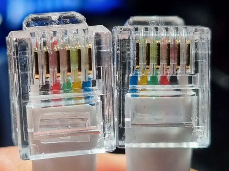
Turns out that there sure was – one connector was installed upside down. This would not be an issue in a phone setting where the cables are designed for use, but in this situation it sure was a problem.
I went to the Internet and downloaded the FT-891 service manual. It was full of information about tuning the radio and schematics. After studying the schematics for a while I was clear what had happened……
If a control cable is installed that has been reversed, then the supply voltage to the control head (on the inner two pins) would also be reversed. That can’t be good.
The other reality set in – This was deliberate damage – outside the terms of the factory warranty for my new 2 month old radio….. Grrr. &*^%*%&^ Jaycar &(^%&*%. I went and had a cup of coffee, and weighed my options.
- I could send it to Yaesu and wait 6 weeks, and pay whatever they decided I needed to pay to recover from the situation. I wonder if they do component level repairs, or if it would simply be board level swapouts?
- I could repair it myself – heck – even if I was unsuccessful I could revert to plan 1.
- I could take it to Jaycar and make it their problem. That was a really unlikely plan.
I decided to look at the problem myself. Soooo here goes.
Step 1 – Send a message to the Book of Faces and see if anybody else had had this issue (that they were going to fess up to) before. That didn’t work by the way.
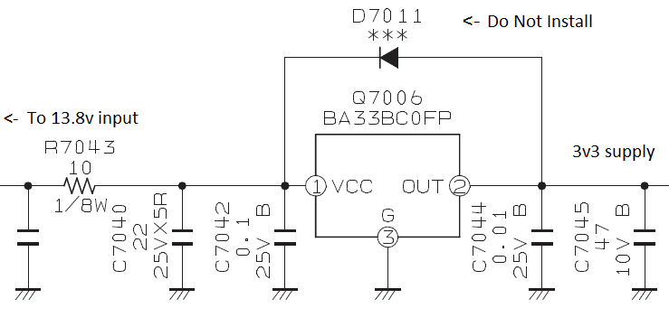
Step 2 – Actually fix the problem. OK – Now onto what the likely damage is within the control head – further study shows that the control head has three separate voltage regulators. 3v3, 5v0 and 9v0 all derived from standard three terminal regulators. Hopefully the reverse voltage only destroyed the regulators. further examination showed that the regulators had protective diodes across them – but these were labeled as Do Not Install…. grrr. Protection removed by saving 4c worth of silicon.
That was all well and good, so I unscrewed the back off the control head and measured the input voltage. Zero – That’s not ideal….
Back to the schematics:
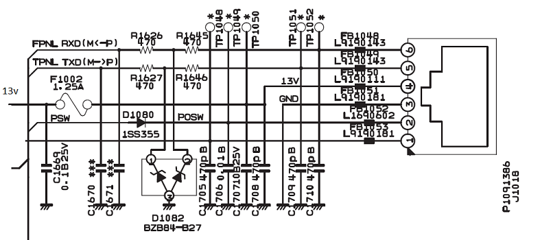
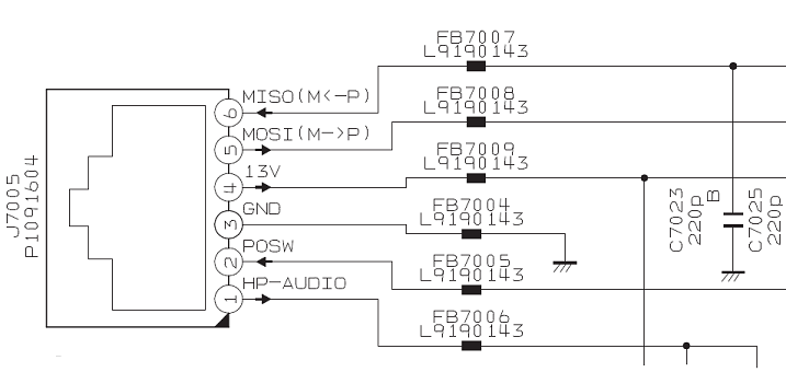
Here you can see that the 13v to the control head is supplied onto pin 4 of the RJ12 – It is protected by Fuse F1002 (1.25Amps).
In my case, F1002 had gone open circuit – protecting the radio from the bad bad cable. That’s not bad design, but gosh the physical fuse was tiny.
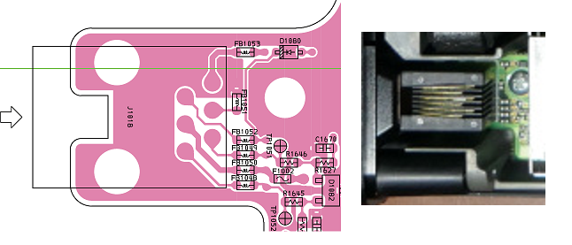
The fuse was a FCC16 132ABTP – A fast acting chip fuse (Rated current x200%, 5s. Max.) 0603, 1.25A. Not the kind of thing I have in my fuse collection. I searched Mouser.com but it wasn’t stocked there. An alternate was made by Bourns MF-FSML125/8 – It is a PTC Resettable Fuse that will mean that I never have to replace that fuse again. The mouser part number was 652-MF-FSML125/8-2 and was $1.57 in units of 10 or more.
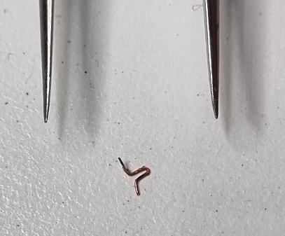
I used a short length of 0.1 mm coil winding wire as a temporary fix until I could order the correct component from Mouser. That gave me 13v at the connector again – Now to continue fault finding.
Plugging in the cable and trying the power again, I discovered that the unit still wouldn’t power up, so clearly the fuse was murdered by some wayward silicon on the control head.
Looking at the control head schematic, I saw that 13V is supplied to three regulators, Q7001 (78L05 5v), Q7006 (BA33B 3v3), and Q7011 (BA09C 9v). I lifted the input to all three regulators, tested again, and still the control head was drawing too much current.
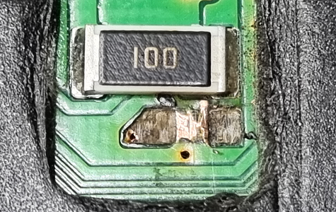
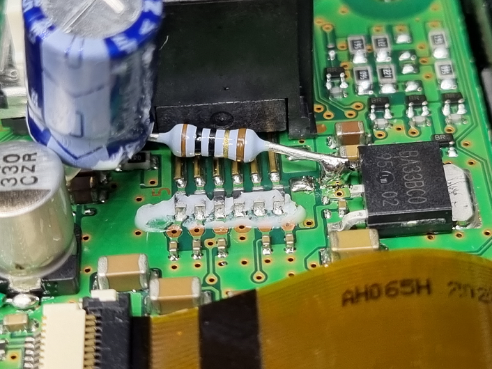
Removing the Control head PCB from the enclosure immediately showed the problem. R7043 (10R, 1/8W) had gotten so hot that it had charred the PCB, letting out all of the smoke, and exuding a conductive black goop all over the back of the board. That explains the excess current.
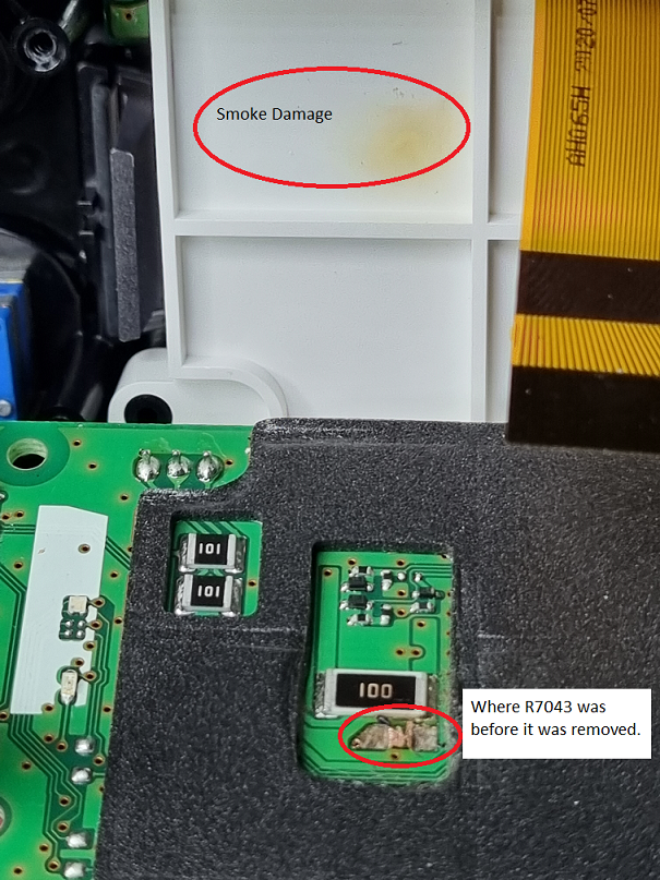
I removed the component , and cleaned up the PCB as best I could, noting that the heat had caused both pads to lift, so any repair was going to have to happen on the top of the PCB. Note also that the black foam didn’t like the heat from the SMD heat gun.
With the component removed, the control head didn’t pull any current at all, so that was clearly the over current culprit. I elected to install a 10R 1/4W resistor on the top side of the PCB directly to the input pin of the 3v3 regulator, and tested the input for shorts. None. Then I decided to reconnect the input of the 5v and 9v regulators and re-test. No shorts – Woot!
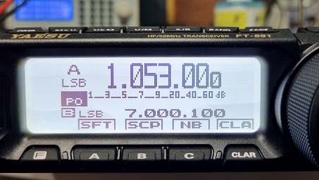
Re-assembling and reconnecting the control head and it was time for the bit test. I pressed the power button and was presented with a beautiful white display. The radio was functional again. Wa Hoo!!!!!
So – now the post mortem. What actually happened?
The reverse voltage being applied to the control head resulted in the inputs to all of the regulators effectively acting as diodes to ground – this put the full 13 volts of the supply across the 10R resistor R7043. 13V across 10R = 1.3 amps. that 1.3 amps through R7043 resulted in it attempting to dissipate 16.9 Watts of heat – It did this enthusiastically (remember its a 1/8 watt part), exuding all of its innards over the back of the PCB and emitting smoke.
Meanwhile the 1.25 amp fuse was merrily holding the 1.3 amps of current, not particularly concerned… until suddenly the goop and carbon from R7073 conducted well enough between the 13v supply and the ground to finally cause the fuse to open. By this time, the PCB had been turned to carbon, and the real damage had been done.
This is a simple example of poor design failing to protect a device from a simple failure. Everything within the control head is powered by voltage regulators – the highest voltage available is 9v and is used to supply the LEDs for TX/RX indication as well as the power to the LCB backlight. If Yaesu had simply installed a reverse polarity diode in series with the input to the control head then none of this would have happened. Sure they would lose 0.7v across the diode, but that would still ensure ample supply to the 9v regulator – even as the input supply of the radio drops below 9v the only thing affected would be the brightness of the LEDs. The radio would stop long before 9v anyway (it is rated for 13.8v +/- 15% or 11.73 to 15.87 volts)
Yes, the Jaycar cable was the root cause, but it’s a dumb enough issue that it has almost certainly happened to others before – a couple of extras cents at the factory and it would not have been a problem.


Great job. Thus is very well written and easy to follow. I’ll store this in my memory bank for when I blow mine up.
The diode across the voltage regulator, if installed, would only protect the regulator during the few milliseconds of power down time. With reverse polarity 13.8V applied to the circuit, the diode would conduct, frying circuits used by the 3v3 bus. The only way the entire control head could be protected (that won’t blow a fuse), would be to place a diode in series with the 10 Ohm resistor. A good reference for these statements is an application note titled “Linear Regulators, Reverse Voltage Protection” from ROHM Semiconductor: https://fscdn.rohm.com/en/products/databook/applinote/ic/power/linear_regulator/linearreg_reverse_voltage_appli-e.pdf
I am also surprised at the application of such a high voltage to a 3-pin 3v3 regulator. Generally, such a large voltage drop by the internal pass transistor would be asking for a failure of the regulator, or at the very least, running very hot.
More Jaycar crap, I purchased a linear power supply from jaycar the transformer was not soldered to the pcb just the wires poked through! Good read glad you got your radio goin!