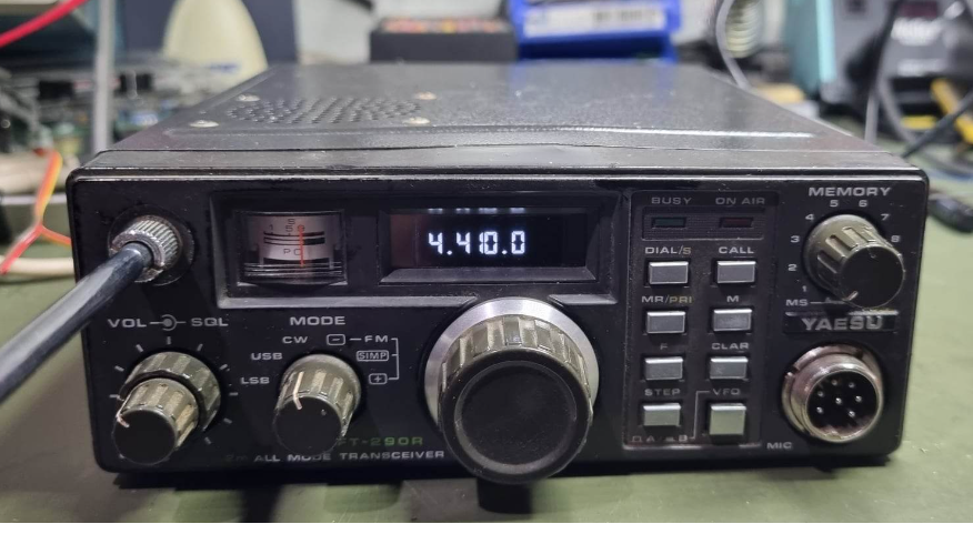
I purchased a Yaesu FT-290R all mode 2M transceiver from an estate sale recently – it was the last item out the door, because it had a faulty LCD display. The radio worked beautifully, although it was marred by a simple fault with the 1980’s LCD display that had the all to common black blotches from leaking making it unusable.
With a bit of searching, I came across a project that Nigel, G6RZR created that replaced the LCD module with an 0.96″ OLED display and an Arduino Nano. (https://g6rzr.com/?page_id=1281) Being a bowerbird, of course I had a handful of displays and Nanos in the parts storage, so I spent an evening disassembling the radio and installing Nigel’s modifications.
One day, I might meet the individual who designed the FT-290, and we will have stern words…. The radio is not designed to have the front removed at all. A couple of web searches was required to remove the front and access the old LCD, but eventually I got there.
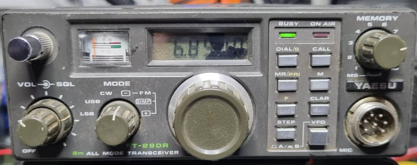
Having installed Nigels screen modification, it simply ‘just worked’ – easy. The quality of the display was spectacular – If you didn’t know it wasn’t factory standard, you would never know. I went to sleep that night happy in the knowledge that the job was done…. but it is never done, is it? – During that night, I decided how cool it would be if the radio also had CTCSS so I could kerchunk the local repeater.
CTCSS
Continuous Tone Coded Squelch System (CTCSS) is a system that used a sub-audible tone in the frequency range from 50 to 300 Hz sent along side the speech from the user to open the squelch in a compatible receiver. It was originally developed to allow multiple radios to share a common frequency, and to allow radios to stay muted if the transmission is not directed at them. Radios would only open their squelch if a compatible time was sent along with the audio. Being below 300Hz, the tone is not audible to the user.
Another use for CTCSS is to enable a repeater to operate in a noisy environment. Often a repeater will have noise on its input frequency – without CTCSS in place, the repeater will constantly broadcast the noise received on the input even without an input signal being present. With CTCSS, the repeater will only transmit when it detects the appropriate CTCSS tone.
There are a number of CTCSS frequencies in use today, specified within a standard by the EIA/TIA. The full list of the tones can be found in their original standard RS-220A, and the most recent EIA/TIA-603-E.
I chose to implement the following list of tones based on examining a number of websites;
67.0, 69.3, 71.9, 74.1, 77.0, 79.9, 82.5, 85.4, 88.5, 91.5, 94.8, 97.4, 100.0, 103.5, 107.2, 110.9, 114.8, 118.8, 123.0, 127.3, 131.8, 136.5, 141.3, 146.2, 151.4, 156.7, 159.8, 162.2, 165.5, 167.9, 171.3, 173.8, 177.3, 179.9, 183.5, 186.2, 189.9, 192.8, 196.6, 199.5, 203.5, 206.5, 210.7, 218.1, 225.7, 229.1, 233.6, 241.8, 250.3,254.1, 270.4Hz.
My local repeater uses a 91.5hz, so I needed CTCSS to be able to access it with my radio.
Generating CTCSS
I had just installed an Arduino into the radio, and it had heaps of spare capacity available, so I chose to generate CTCSS by using Pulse Width modulation, using one of the Arduino Counter/Timer modules. This would ensure that the Arduino could create the relevant tone, while requiring minimum resources and continue to display the set frequency.
In order to generate a sine wave, I needed to use a wave table that could describe the sine wave. In software, I generated the sine wave using a simple Sine wave lookup. this models a sine wave of the required frequency in an array called waveTable.
for (int index = 0; index < SamplesPerCycle; index++)
  {
  waveTable[index] = Amplitude * sin(TwoPi * index / SamplesPerCycle) + Offset;
  }
The generation is then done using a Counter Timer, specifically Timer 2. I setup an Interrupt Service Routine (ISR) which writes the next element of the wavetable into the Timer Compare register
ISR(TIMER2_OVF_vect)
{
OCR2A = waveTable[waveIndex]; //Write the current wavetable index
waveIndex++;
if (waveIndex==SamplesPerCycle) waveIndex=0;
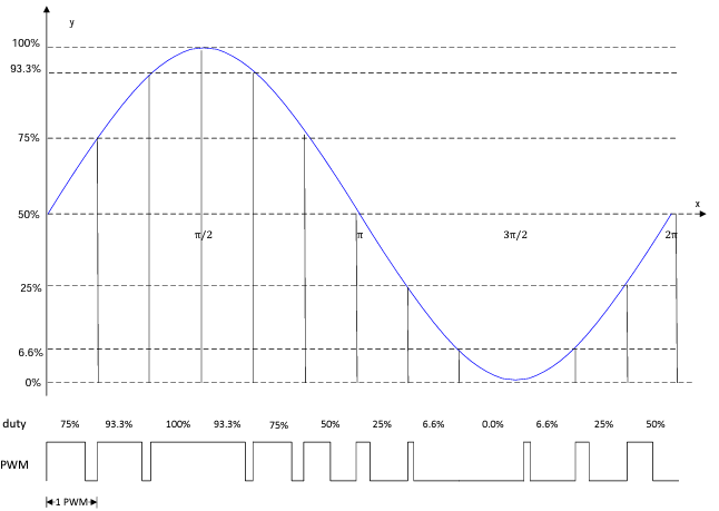
}The following diagram from a Texas Instruments application note provides a great representation of the translation between PWM values and a sine waveform. The longer the PWM value, the higher the waveform becomes, while the shorter the value, the lower it gets. The length of the PWM period is encoded into the wavetable.
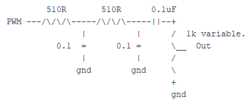
The PWM output is filtered using a Low Pass Filter as shown below.
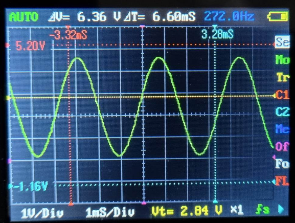
Here is a 272 hz tone, after filtering.
Controlling the CTCSS frequency
Having generated the waveform, it was important to be able to control it. I needed a way of setting the appropriate frequency. Nigels code provided me with the ability to detect when the radios dial had been rotated by watching the 10Khz digit. I just needed to detect a button push to put the software into a ‘setup’ mode, and monitor the digit to allow the CTCSS tome to be selected from a table of tones.
I used a table stored as a set of integers that the CTCSS display routine could step through. Storing it as integers resulted in less memory being used, but care had to be taken to divide the table value by 10 before it was used.
const int   CTCSSMax=52;    // there are 52 elements in this CTCSS Table (stored as
                            //  10 * integers to save space as storing floats
                            //  costs memory i.e.   915 = 91.5 Hz )
const int   CTCSSTable[CTCSSMax]={0, 670,  693,  719,  741,  770,  799,  825,  854,
                                  885,  915, 948,  974, 1000, 1035, 1072, 1109,
                                 1148, 1188, 1230, 1273, 1318, 1365, 1413, 1462,
                                 1514, 1567, 1598, 1622, 1655, 1679, 1713, 1738,
                                 1773, 1799, 1835, 1862, 1899, 1928, 1966, 1995,
                                 2035, 2065, 2107, 2181, 2257, 2291, 2336, 2418,
                                 2503, 2541, 2704} ;
I defined two input pins – one for the CALL button, and one for the FMTX line.
The CTSS Setup routine is accessed by pressing the CALL button, resulting in the currently selected CTCSS frequency being shown on the display. Once the CALL button is pressed again, the currently selected CTCSS value is written into EEPROM on the Arduino, so it is permanently in place.
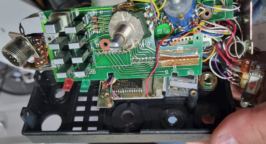
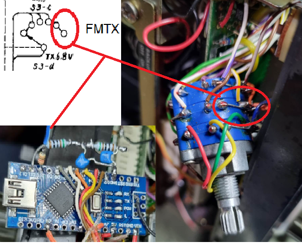
I found that when the CTCSS tone was being generated, the display update was lethargic – cycles were being stolen from the Arduino, so the display wasn’t being updated reliably – To aleviate this, I decided to only enable the CTCSS generator when the radio was transmitting in FM mode. I found a FMTX signal in the radio that served this function beautifully.
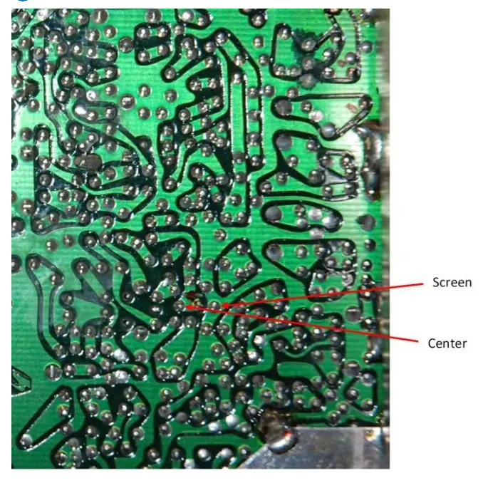
Finding the FMTX line involved removing the front of the radio again, as it was available on the multifunction switch. The following photos show where I made the connections;
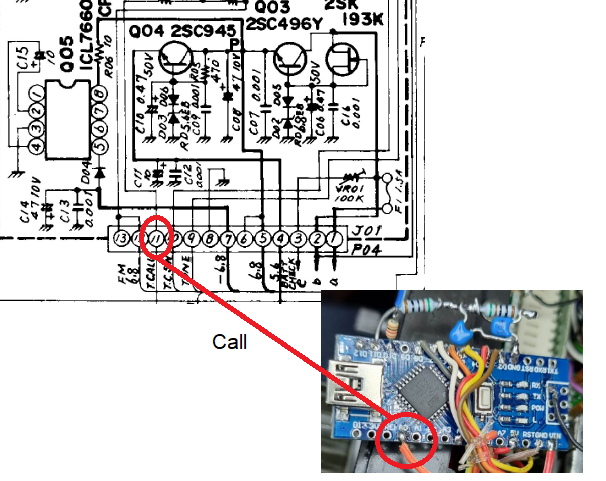
The call button is easier to locate – it is available on the Power supply board. Simply remove the battery housing and make a connection to the third connection from the edge:
CTCSS Audio Injection
Following instructions provided by G4KQK, i used the audio injection point he did for his CTCSS module. I coupled the audio from the Arduino out via a 0.1uf capacitor.
A bit of a physical cleanup of the wiring, and I hit the TX for my local repeater on 146.900Mhz, and Kerchunk, it came right back.
SUCCESS! Another FT290 is alive and entering the 21st century happy as larry!
The code:


G’day, Doug!
Thanks for posting that! I saw one of these at a local swapmeet yesterday but refrained from buying it because I have the 6m version of this radio. The frequency isn’t very stable. Mine drifts annoyingly.
Since you have an Arduino in there now, and the CTCSS is accomplished, have you considered having the Arduino manage the frequency synthesizer? Instead of the coarse PLL divider and resistor-network DAC feeding a varicap diode, you could have the Arduino control an Si5351A running from a TCXO and have the frequency spot on all the time.
Doing something like this is on my list of upcoming challenges. But if someone has done part of the engineering already, it’d make the project shorter and help it rise on my list.
Halden VE7UTS
Hi Doug,
what a wonderful project. I was about o make the version without CTCSS but when i saw yours i had to do it. Just put the code and all ok. I still haven´t placed on the radio, maybe tomorrow. One doubt and one sugestion 🙂 . I can read Arduino codes but not programing well. I think A0 goes to ground to activate CTCSS?
Now the sugestion…lol… i have a mic that came with the radio, “YM47” that has two buttons on top: UP and DWN. Never used nor have any intention of using. What you say if they would make the tones go up or down? In that way wrong frequencys beeing displayed would be avoided since the frequency dial button was not used. If you don´t think this is a good idea or dont want to have that trouble, can you please guide on what i should try to change in the firmware?
PS: my idea was to use two more pins on the arduino and unsolder the Up/Dwn wires from the radio mic plug.
So, thats it. I really love this radio, even bought another for transverter use.
PLS tell me something. Best regards and 73’s from José/CT1BRN.
Oh wow, well done! I have just purchased a FT 290 myself and both of these mods will be perfect for my little radio, thank you.
Hi doug I felt compelled to thank you for publishing the details of the modifications to bring the yaesu ft290r into the 21st century.
I found your mods fascinating and I do have oled screens and an arduino nano knocking around my shack. i think im going to delve right in and have a go. I think mine needs a recap to it takes a few minutes to get any audio out of it but once it been on for a while it all work OK.
Thanks again kindest regards
Simon 2E0HYP
Hi Simon, Thanks for the wonderful feedback – I really enjoyed this project.