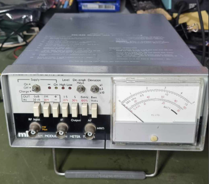
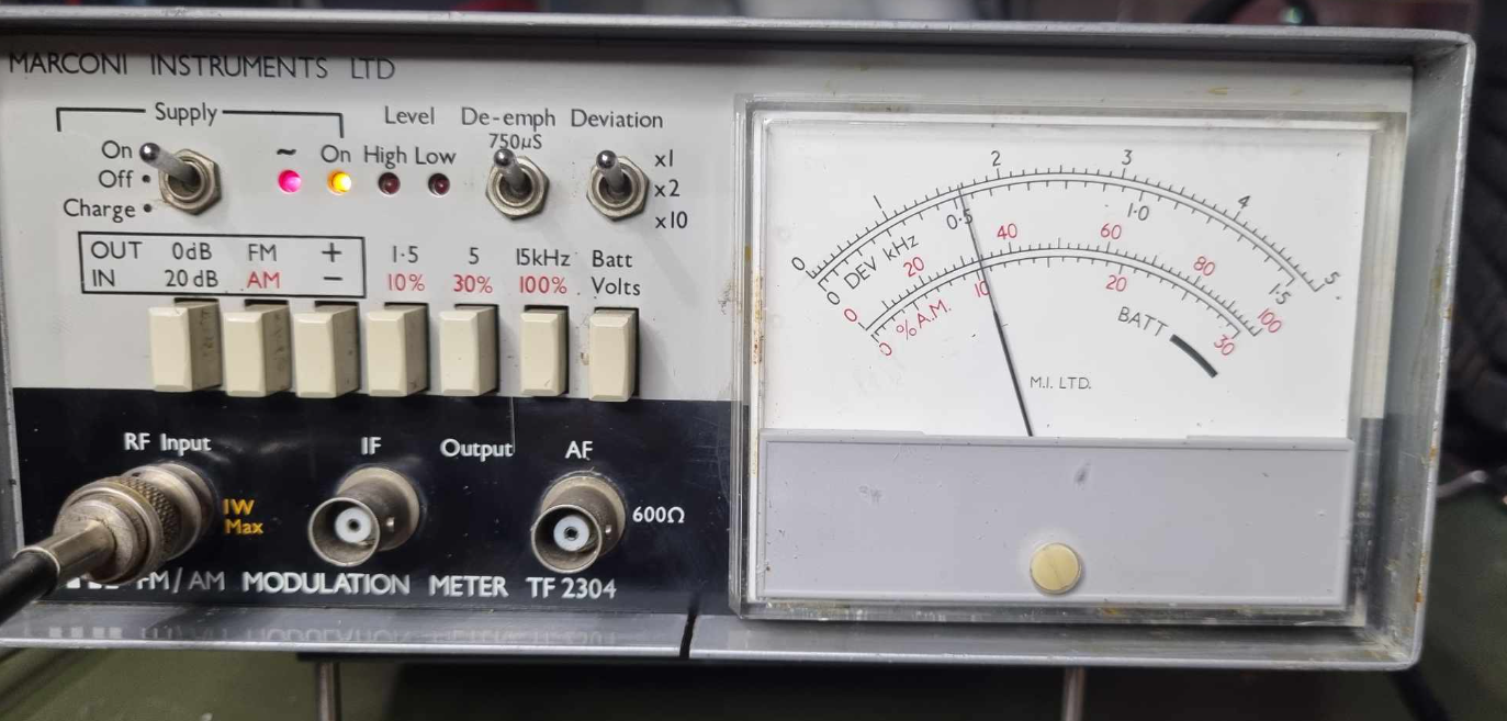
A while ago, I got a cheap modulation meter from eBay from a chap in the UK – It was made by Marconi, and was a beautiful piece of gear. Unfortunately, the unit had seen better days, the meter was held in by contact cement, and somebody had transmitted into it, damaging its front end.
I had a bit of a look at it when it arrived, and repaired the easy damage, cleaning it up significantly, but because I didn’t have a reliable RF source, apart from whistling into a transmitter, I decided that repairing it would have to wait till I had better gear.
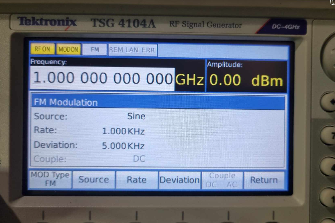
Recently, I was able to get an ex demo Tektronix TSG-4104 RF generator, which is quite nice – DC – 4Ghz with heaps of modulation methods (including AM and FM), so it was finally time for me to spend some quality time working on my Modulation Meter.
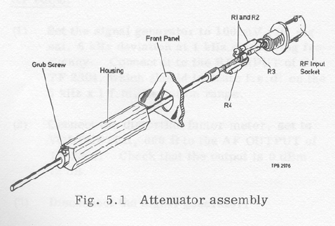
Firstly, I examined the 20DB attenuator built into the read of the input socket, and it was clear it had been cooked properly – Somebody transmitted into it for an extended period of time with way more than the recommended 1Watt of input. The 120 Ohm input resistors that were in parallel were open and cooked. I replaced them, and the input sprang into life.
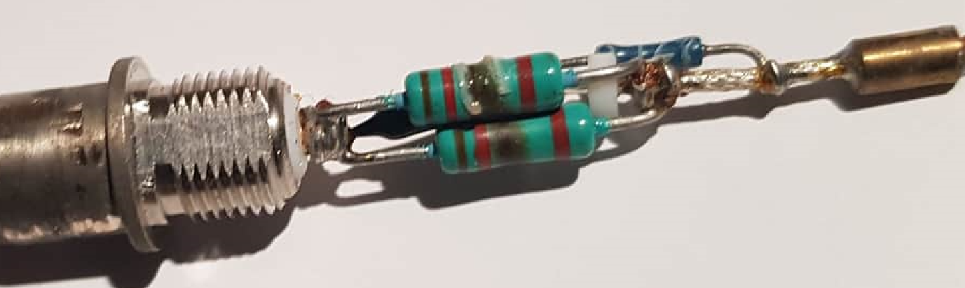
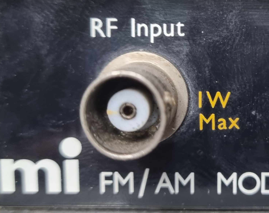
The same BNC that says 1Watt MAX… Maximum….. Not 1Kw…
Next, I performed a quick check of its operation, and the Low Level input LED wouldn’t turn off, indicating that the AGC on the devices IF wasn’t seeing enough of a signal. The block diagram let me know what the signal path looked like, so working on the basis that the device had been overloaded, I started looking at likely culprits.
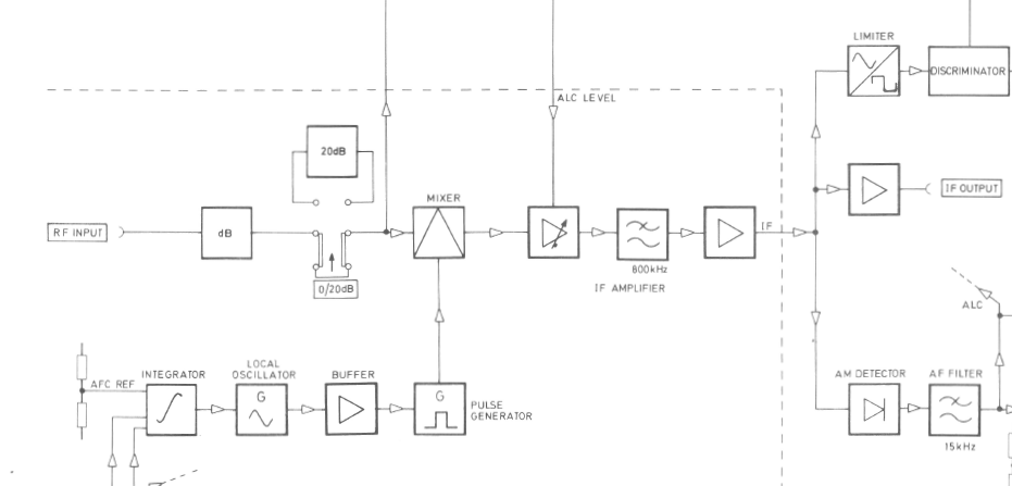
The Mixer was the next to be looked at, and it used a fairly interesting diode arrangement, switched on and off by the very fast rise time LO signal (fed via a pulse generator diode D7, creating a very rich harmonic content), allowing the meter to lock onto input signals up to about 1Ghz. I could see great pulses into Transformer T1, but nothing that looked like an IF output into the gate of TR5. Immediately, I looked at the Schottky diodes, D8 and D9, and sure enough they had reverted to sand. A quick search through my parts found some suitable replacements, and I started to see a slightly better output at TP7, but still it did not look ok.
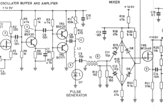
I measured the gate resistance of TR7 (should have been Open – but it looked like it too had been damaged, so I did a quick swap out with a humble MPF102, and I immediately saw better IF signals, but the device still wouldn’t lock.
I stopped working on it on Saturday morning, as I had to go out, and late on Sunday, I picked it up again. I wondered if the Transformer T1 had been damaged, and sure enough, I saw an open winding. T1 is critical to the mixer, as it converts the pulse output from D7 into a +ve swing, and a -ve swing to cause the D8/D9 pair to turn on, performing a mixing action.
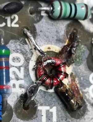
I was lucky that the open winding was located at the end of the transformed, where the wire entered the board so it was a simple matter of removing the open end, inserting a component lead, and soldering on top of the board. The transformer was tiny, with the ferrite being about 4mm diameter.
After repairing he transformer, the device sprang into life.
A quick test showed that it was even within calibration, showing 5khz deviation at 100 Mhz, and 1Ghz.
In all, I am beyond happy I now have a real modulation meter that I can use to get the modulation output of my TNC’s correct – Only 40 years after the heady Packet Radio days, but that’s not the point 🙂
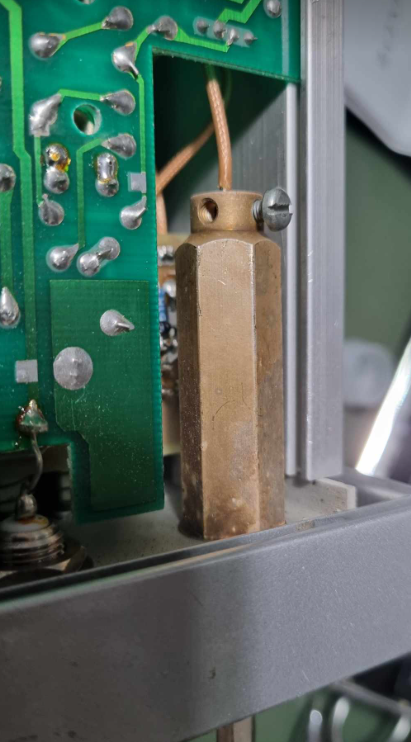
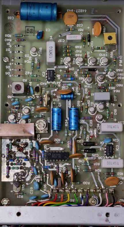
For interest, here are a couple of photos of the internal layout of the meter – it is typical of high quality test equipment of the mid 70’s.
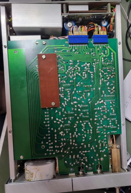
This is the RF board that does all of the signal processing – it is normally shielded. you can clearly see the mixer transformer and diodes, as well as the faulty TR5 in the bottom left corner.
To those who automatically replace capacitors – the Phillips caps in this unit are as good as the day they are made. No stolen formulas there 🙂
In all, it was a wonderful evening – and I am very happy.