I have a couple of old paper tapes – I also have an ASR33 teletype, which is more than capable of reading a tape, but making the ASR33 operate correctly is a labor of love which I will complete Before-I-Die ™.
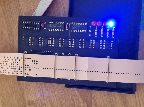
One project I was able to obtain a while ago was a reproduction of an optical tape reader originally made by Oliver Audio Engineering (OAD) called the OP-80A. The OP-80A uses an optical read head consisting of a set of photo transistors that monitor every bit of the tape, including the sprocket hole. As a tape is pulled through the reader different data patterns are presented to the read head. When a light pulse is detected by the sprocket hole sensor, a RDY flipflop is asserted to let the host computer know that data is ready to be read. Depending on how fast the tape is being dragged, you have a reasonable number on Milliseconds to read the data, and clear the flip-flop by toggling the ACK* signal.
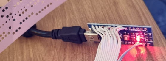
I decided that I would interface the OP-80A that I had to an Arduino – That would provide me with the ability to read tapes and output them using the built in serial port capability of the Arduino. Easy. I have a box full of Arduino boards, so i chose an Arduino nano because it was small enough to fit into the existing enclosure that the OP-80A was mounted in.
Firstly – I identified the pinout of the OP-80A interface. Michael Holley did a wonderful scan cleanup of the original manual in 2001. It is available here: https://deramp.com/swtpc.com/OAE80_Reader/OAE_80A_Manual.pdf
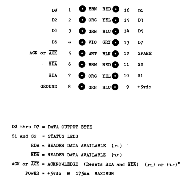
I cut a short 4 inch length of 14 conductor ribbon, and wired the Arduino to the OP-80A using the following schema.
LED - S1 -> Arduino A0
- LED_S1 -> Arduino A0
- LED_S2 -> Arduino A1
- D0 -> Arduino D3 (D0 & D1 are used for the TX/Rx pins of the Arduino)
- D1 -> Arduino D4
- D2 -> Arduino D5
- D3 -> Arduino D6
- D4 -> Arduino D7
- D5 -> Arduino D8
- D6 -> Arduino D9
- D7 -> Arduino D10
- RDA -> Arduino D11
- ACK*-> Arduino D12
Next, I fired up the Arduino IDE and wrote a short test program to flash the S1 and S2 LEDs to verify I had the wiring correct;
//
//OP-80A test - Blink S1 and S2
//
const byte LED_S1 = A0;
const byte LED_S2 = A1;


void setup() {
  // put your setup code here, to run once:
  // initialize digital pin LED_S1 and LED_S2 as outputs.
  pinMode(LED_S1, OUTPUT);
  pinMode(LED_S2, OUTPUT);
}

void loop() {
  digitalWrite(LED_S1, HIGH);   // turn the LED on
  digitalWrite(LED_S2, LOW);    // turn the LED off
  delay(1000);                  // wait for a second
  digitalWrite(LED_S1, LOW);
  digitalWrite(LED_S2, HIGH);

  delay(1000);                  // wait for a second
}
That was loaded up and I was instantly rewarded with the status LEDs blinking – I can still write Arduino C Code !!!! Wohoo!
Next, I created this code to actually read the data as it became available – It simply reads the input pins, builds an output character and prints it @ 9600 baud on the USB serial port. You will see the code that outputs the individual bits – its commented out for normal operation.
//
//  OP-80A Interface controller
//
// Input: OP-80A board - Output: USB com port
//
// Copyright 2022 - Doug Jackson - VK1ZDJ
// Others are welcome to build upon this code.

// Read in a tape - One byte at a time
// When RDY goes high, bit shift D10-D3 down 3 bits to be D7-D0 and output that as a byte
// then toggle ACK* line to reset RDY flipflop.
// then do it all again

// Status LEDS connected to A0 and A1 don't do anything.

const byte LED_S1 = A0;
const byte LED_S2 = A1;
const byte IN_D0 = 3;
const byte IN_D1 = 4;
const byte IN_D2 = 5;
const byte IN_D3 = 6;
const byte IN_D4 = 7;
const byte IN_D5 = 8;
const byte IN_D6 = 9;
const byte IN_D7 = 10;

const byte RDA = 11;
const byte ACK = 12;


void setup() {
  // put your setup code here, to run once:
  // initialize digital pin LED_BUILTIN as an output.
  pinMode(LED_S1, OUTPUT);
  pinMode(LED_S2, OUTPUT);

  pinMode(IN_D0, INPUT);
  pinMode(IN_D1, INPUT);
  pinMode(IN_D2, INPUT);
  pinMode(IN_D3, INPUT);
  pinMode(IN_D4, INPUT);
  pinMode(IN_D5, INPUT);
  pinMode(IN_D6, INPUT);
  pinMode(IN_D7, INPUT);
  pinMode(RDA, INPUT);
  pinMode(ACK, OUTPUT);

Serial.begin(9600);
Serial.println("Ready for input");

Serial.println("Resetting ACK");
digitalWrite(ACK, HIGH);
delay(5);
digitalWrite(ACK, LOW);
digitalWrite(ACK, HIGH);

}

void loop() {
  // put your main code here, to run repeatedly:
char character;


if (digitalRead(RDA)!=0)
{

//Serial.println("Got a RDA");

character = digitalRead( IN_D7 ) << 7;
//if(digitalRead( IN_D7) ==0) Serial.print('0'); else Serial.print('1');

character += digitalRead ( IN_D6 ) << 6;
//if(digitalRead( IN_D6) ==0) Serial.print('0'); else Serial.print('1');

character += digitalRead ( IN_D5 ) << 5;
//if(digitalRead( IN_D5) ==0) Serial.print('0'); else Serial.print('1');

character += digitalRead ( IN_D4 ) << 4;
//if(digitalRead( IN_D4) ==0) Serial.print('0'); else Serial.print('1');

character += digitalRead ( IN_D3 ) << 3;
//if(digitalRead( IN_D3) ==0) Serial.print('0'); else Serial.print('1');

character += digitalRead ( IN_D2 ) << 2;
//if(digitalRead( IN_D2) ==0) Serial.print('0'); else Serial.print('1');

character += digitalRead ( IN_D1 ) << 1;
//if(digitalRead( IN_D1) ==0) Serial.print('0'); else Serial.print('1');

character += digitalRead ( IN_D0 ) ;
//if(digitalRead( IN_D0) ==0) Serial.println('0'); else Serial.println('1');

Serial.print(character);


// Ack the read byte
digitalWrite(ACK, HIGH);
delay(5);
digitalWrite(ACK, LOW);
digitalWrite(ACK, HIGH);
}

}
After a bit of testing, I cut a small hole in the back of the OP-80A enclosure and secured the arduino in the botton – Now the OP-80A looks stock, but it has a USB interface built in 🙂
I was able to read in a couple of unknown tapes that came with my Dream 6800 system – they are intel Hex dumps of the 2708 roms on the board.
:10110000DE2620090F9F129E2634CE0030D62BC437
:101110000F32A700087C00275A2AF69E120E39D6F5
:10112000297F003FDE268601971CC40F2602C610C9
:1011300037DF14A600971E7F001FD62EC40727098D
:1011400074001E76001F5A26F5D62E8D28961E8D09
:1011500015D62ECB088D1E961F8D0B7C002FDE140E
:1011600008335A26CB3916E800AA00E700112704F5
:101170008601973F39962F841F484848C43F5454EE
:10118000541B971DDE1C39C6F0CE80106F01E7009E
:10119000C606E7016F00398DEE7F00188D55E60019
:1011A0008D159717C60F8DE1E600545454548D07E2
:1011B00048489B17971739C10F2602D71886FF4C4E
:1011C0005425FC39DF128DBFA6012B07482AF96D83
:1011D0000020078DC27D001826EC8D03DE1239C673
:1011E00004D721C641F780127D002126FBC601F7F6
:1011F0008012398D0037C6C85A0126FC3339CE809B
:1012000012C63BE701C67FE700A701C601E7003928
:101210008D13A6002BFC8DDDC6090D6900468DD30C
:101220005A26F72017DF12CE8012398DF8366A0061
:10123000C60A8DBFA7000D465A26F732DE123920A6
:101240008386378DB9DE02398DF7A6008DDD089CC7
:101250000426F7200B8DEA8DB7A700089C0426F71B
:101260008E007FCEC3E9DF00863F8D928D430E8DC9
:10127000CE4D2A108DC9840327234A27D84A27C870
:10128000DE066E008D0C97068D0697078D2320DFF6
:101290008DAD48484848970F8DA59B0F398D12DEBC
:1012A000068D258D9A4D2B048DE8A70008DF0620BA
:1012B000EC86108D2BCE01C886FFBDC07DCE00060A
:1012C0008D06088D038D1539A60036444444448D9F
:1012D0000132DF12BDC193C6058DC22486049B2E48
:1012E000972E861A972FDE12397A00207A00217DF8
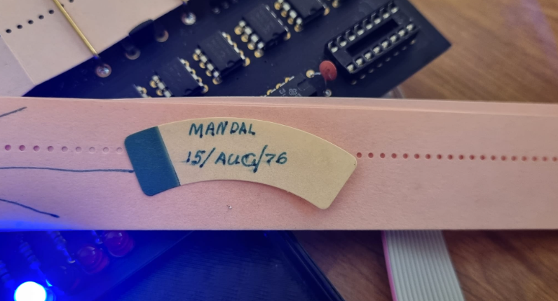
:1012F00080123BDE006E0000C3F300800083C360F9I was also able to read a Mandal program that was on tape – the tape was from 1976 – I was 10!!!
10 DIM C$(6),A$(3)
12 C$ ="*.  $#"
14 P1=3.14159
22 PRINT
24 PRINT"  ** YOU **   DESIGN A MANDALA BY TYPING IN SOME NUMBERS."
26 PRINT
100 REM ** INITIAL DIALOG **
110 PRINT
120 PRINT "SIZE OF MANDALA IN INCHES ";
130 INPUT S
135 LET S8=S
140 IF S>=1 AND S<=7 THEN 180
150 PRINT "MANDALAS CAN BE BETWEEN 1 AND 7 INCHES."
160 PRINT "SIZE ";
170 GOTO 130
180 S=INT(2.5*S-.5)
190 PRINT "DIP FREQUENCY AND IMPORTANCE ";
200 INPUT F1,C1
205 LET F8=F1:C8=C1
210 PRINT "RIPPLE FREQUENCY AND IMPORTANCE ";
220 INPUT F2,C2
225 LET F9=F2:C9=C2
230 PRINT "COMBINATION IMPORTANCE ";
240 INPUT C3
245 LET C7=C3
250 PRINT
260 PRINT"HERE IS YOUR MANDALA :"
270 PRINT
280 REM *** PARAMETER NORMALIZATION ***
290 F1=INT(F1+.5)
300 F2=INT(F2+.5)
310 C1=ABS(C1)
320 C2=ABS(C2)
330 C3=ABS(C3)
340 C=C1+C2+C3
350 C1=3*C1/C
360 C2=3*C2/C
370 C3=3*C3/C
380 PRINT
1000 REM *** PRINTING LOOP ***
1010 FOR Y=S TO -S STEP -1
1020 Y2=Y*Y
1030 REM FIND EDGE
1040 X1=S
1050 X2=-S
1060 X3=-1
1070 FOR X=X1 TO X2 STEP X3
1080 R=SQR(X*X+Y2)/S
1090 IF X <> O THEN 1120
1100 A=P1* SGN(Y)/2
1110 GOTO 1150
1120 A=ATN(Y/X)
1130 IF X>0 THEN 1150
1140 A=A+P1
1150 G1=SIN(F1*A)
1160 G2=SIN(F2*R*P1)
1170 Q=INT(C1*G1+C2*G2+C3*G1*G2+3)+1
1180 IF X3=1 THEN 1250
1190 IF Q=3 ORQ=4 THEN 1260
1200 REM FOUND EDGE
1210 X1=-S
1220 X2=X
1230 X3=1
1240 GOTO 1070
1250 PRINT MID$(C$,Q,1);MID$(C$,Q,1);
1260 NEXT X
1270 PRINT
1280 NEXT Y
9999 END
This is the same code as I found on the Microbee website – but the Microbee version was attributed to ROM B/GCC III. It also had a number of dropped spaces that caused MBASIC to barf – things like 140 IFS>=1 AND S<=7THEN 180 which should have a space between the IF and S> terms.
0 REM                M A N D A L A
1 REM
2 REM  MANDALA   REDONE      VER 1.3     9/20/76      ROB C/GCC III
10 DIM C$(6),A$(3)

etc....
To use this, simply plug it into the PC – Load up your favourite terminal program. Load the tape, put a desk lamp above the reader and pull the tape through. I found that I could stop pulling and move my hand back to pull the next length and it was not an issue – This is because the RDA flip flop waits for a dark-light transition before triggering again.
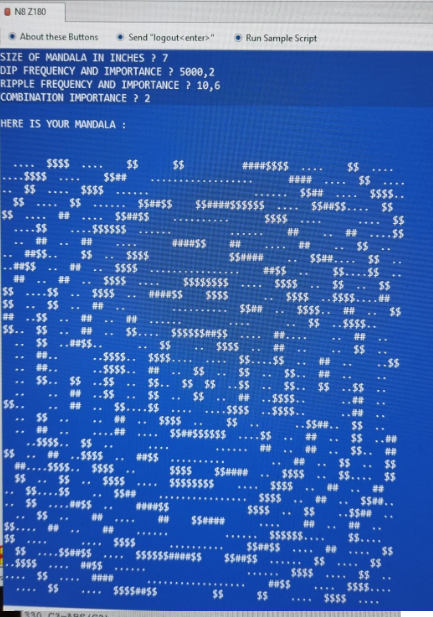
Oh – If anybody is curious what the Mandala output looks like – I loaded it into my N8 CP/M system and executed it under MBASIC. Here is a sample run.
In all, not a bad afternoon. Now – To continue working on the ASR-33 :-).

