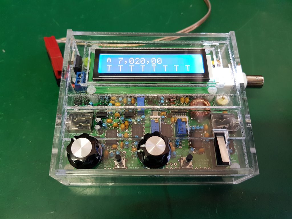
I have recently obtained a neat little radio from the clever folk at QRP Labs – the QCX-40. https://qrp-labs.com/qcx.html It is a single board CW transceiver, designed to operate on a single band from 80m through to 17m selected at build time by winding various torroids and selecting appropriate band pass capacitors.
The transceiver is microprocessor controlled, and uses an Si5351A based frequency synthesizer for its VFO with a rotary encoder to allow easy tuning. The single board is fairly well packed with components, but simple to assemble.
Being an experimenters radio, it is not particularly enclosure friendly – the volume knob is at one height, the encoder is at a different height, the selection buttons are at another height, and finally the LCD display is at a third height. The radio does have the capability of having the controls mounted off board, by providing PCB pads for soldering remote controls, but I had already soldered my controls in place.
In various reviews, including a brilliant video blog episode #109 by Dave Kelser (k0og) https://www.youtube.com/watch?v=A0BkDoVcaQ4, various presenters say that the board is difficult to make an enclosure for. That was enough of a challenge for me! I decided I would design a small enclosure using clear acrylic that truly shows off my radio. My enclosure isn’t waterproof, but then neither am I :-).
I decided to make the front panel of the enclosure using a series of three joined acrylic pieces, accommodating the height differences of the components. I was fortunate that when I built my radio that I used a fairly tight bending radius on my resistors, and they cleared the top of the rotary encoder body as far as height was concerned. I replaced the selection push buttons with long shaft versions (15mm shaft) allowing them to protrude the enclosure beside the tuning encoder. The volume control is a tight fit, as there is only 4mm of shaft available but that is certainly acceptable..
I had to provide relief holes in the lowest level of the acrylic for the microswitch as well as the three potentiometers. The potentiometers are protected by the second transition layer of acrylic that leads up to the LCD display.
A view of the side of the enclosure clearly shows the terraced arrangement of the face pieces, building up height to cover the LCD screen. I used long cutouts to allow the sides of the enclosure to allow it to simply slide down over the radio, being held in place by the base which is screwed into the PCB supports provided by QRP Labs.
My enclosure was cut out using a 30W laser cutter to cut my 3mm acrylic, and I used Acribond professional acrylic solvent to glue the parts together. In all the assembly took about 10 minutes, while the design was a morning 🙂
Before I installed the base of the enclosure, I soldered a short extension cable and an Anderson connector to the power input to allow me to power the radio. I love the Anderson concept, they work so much better than banana plugs, and they automatically provide reverse polarity connection when the entire shack, as well as my portable batteries are wired with them.
There is scope to improve the design by providing tabs to seat the terraced face components in the side supports, but that is for next weekend. In the meantime, there is a download of the SVG file that I used to make this version of the enclosure available here:  . You are very welcome to approach somebody you know who has a laser cutter to make one for you, or use a laser cutting bureau like Ponko.
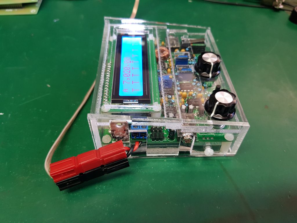
The Left side of the radio showing the Anderson plug – I have to screw that to the enclosure for better support.
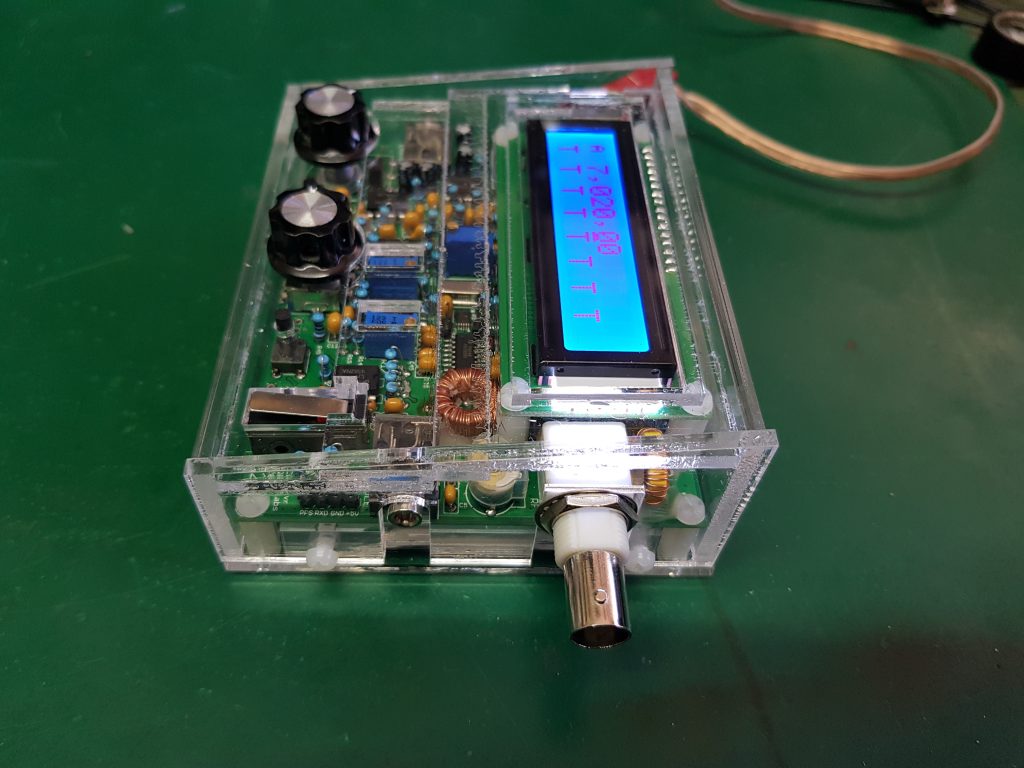
The right side showing the cutouts for the BNC socket and Key jack. Fortunately, the 3mm acrylic width doesn’t obscure the jacks.
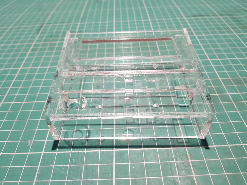
Detail of the front view of the overall enclosure minus the base without it mounted on the radio.
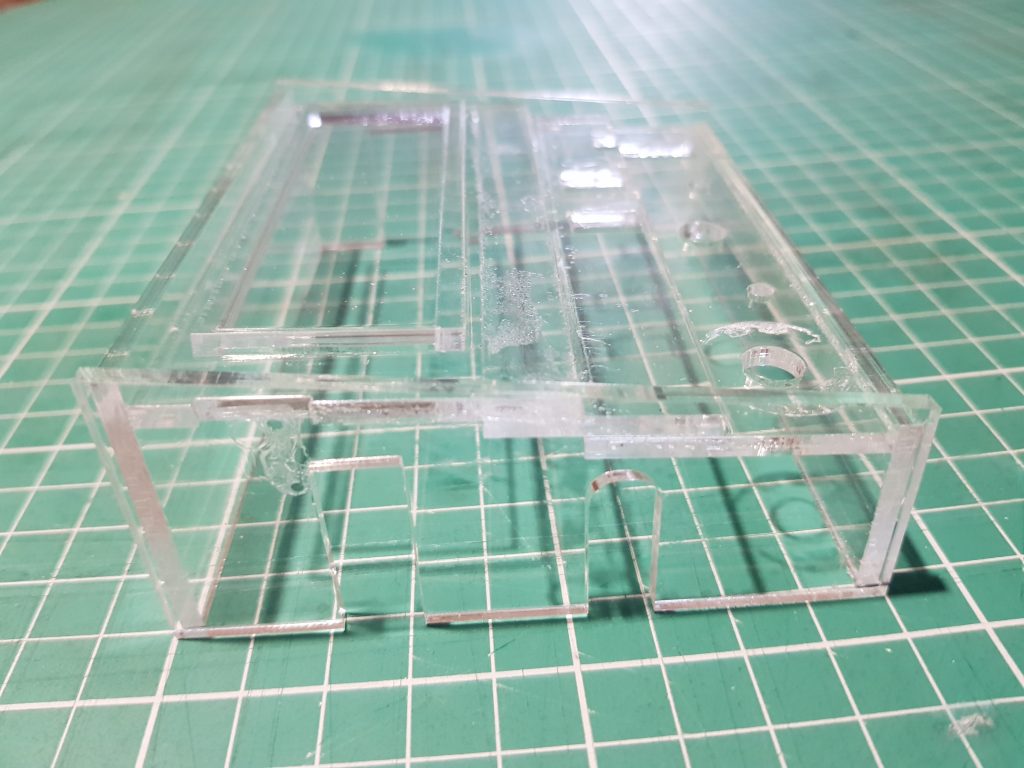
The left side of the enclosure without it mounted on the radio. Here you can see the various levels of acrylic forming the face of the radio – also note that the acrylic is mounted at an angle (i.e. not parallel to the base)


Looks very nice. Will done!