
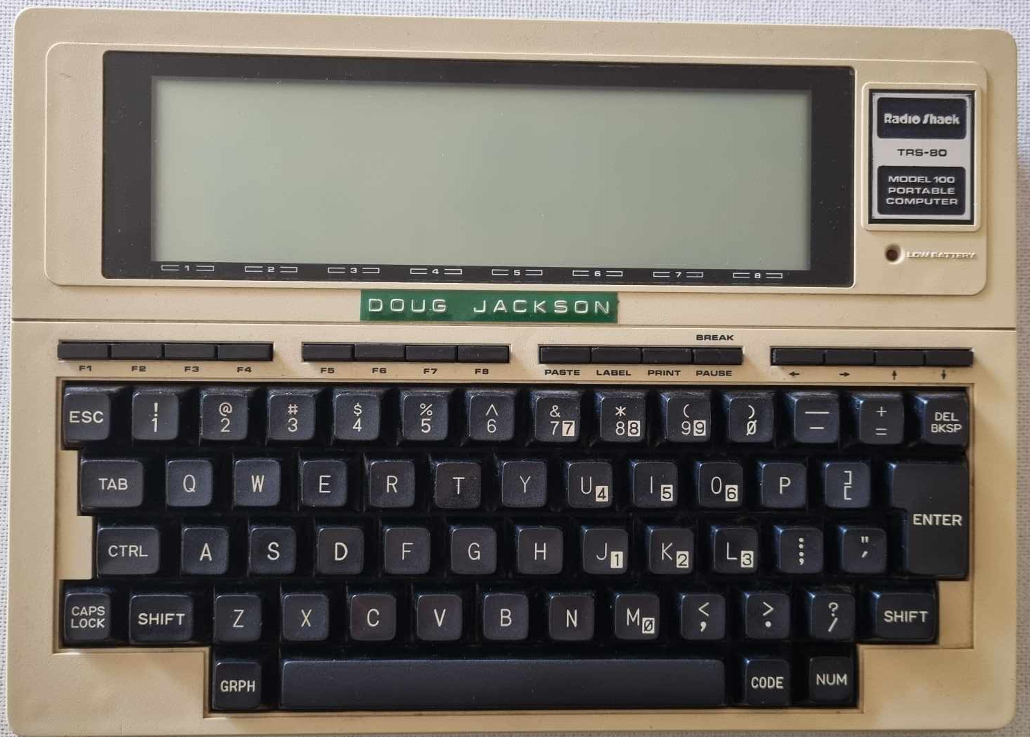
In my teenage years, I was lucky to do some programming work for the Australian National University which resulted in me being able to purchase a TRS-80 Model 100 computer. It was an amazing machine supporting 32K of inbuilt RAM, an 40 x 8 LCD display, and able to be powered from a set of 4 AA batteries.
I used the machine extensively, but one frustration was that the inbuilt modem was designed to support the BELL 103 tones, not the CCITT V21 tones used in Australia. The MC14412 itself could generate and decode CCITT V.21, but the analogue filters around it had been designed for the Bell 103 frequency bands. Changing the modem standard therefore meant changing both the MC14412 mode selection and retuning the filters. At the age of 16, I wasn’t about to change that, so I simply used a SendData Acoustic coupler to allow me to dial into BBS machines and the Schools Authority PDP/11. There is a reason why my day job is in IT security 😉
Fast forward a couple of years, during which time I went to TAFE and studied electronics, as well as getting a job at the ANU as a Trainee Technical Officer. That provided me with a massive understanding of how Operational Amplifiers work, so I could finally address the pesky filter issue.
This post is me documenting those changes from random scraps of paper stuffed into the TRS80 Model 100 Technical Reference Manual I have here.
Bell 103 vs CCITT V21
In the heady 60’s, 70’s and 80’s there were two common standards for sending 300 baud data across telephone lines. Bell laboratories in the USA had a standard called Bell 103, which used two sets of tones (one for sending and one for receiving- The originating station would send 1070Hz / 1270Hz , while the answering station would send 2025Hz / 2225Hz. The use of two tone pairs allowed data to be sent bidirectionally at the same time.
The Europeans chose a different set of tones for their CCITT V21 Standard – The originating station would sent 980Hz / 1180Hz, while the answering station would send 1650Hz / 1850Hz. Again, two tone pairs allowed full duplex communication.
It is this different frequency set that stopped my internal modem from operating.
The Transmit Filters
The ensuing years have made documenting things so much simpler – Thanks to Henner Zeller, I have some great diagrams that I can use portions under the Creative Commons Attribution-ShareAlike CC-BY-SA 4.0 license. https://github.com/hzeller/trs80-100-schematic
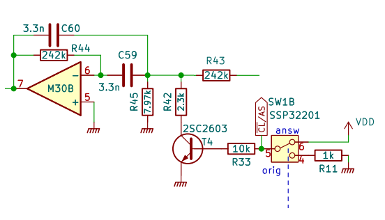
This is the Transmit filter – We will use it to look at first, because it is simpler:
The general form of this filter is:
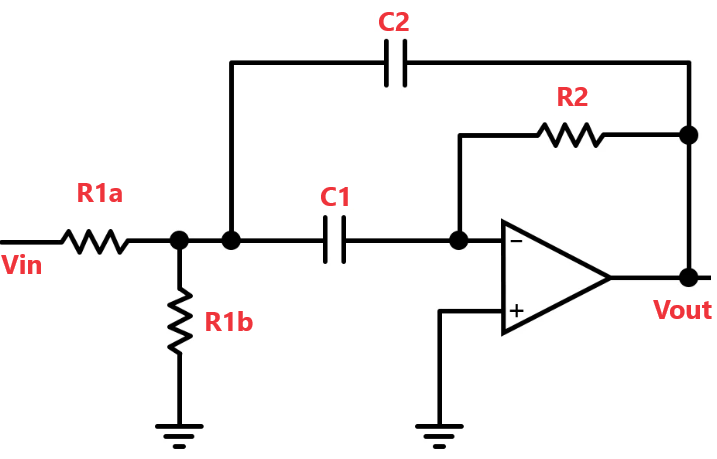
When C1 = C2, the center frequency of this type of filter is derived by:
C = C1 = C2. R1 = R1a || R1b

In the example above, when in Originate mode, fo = 1.1KHz, Bw = 2.50Khz and Q = 89.28E-03 – That lines up with our expectation of sending out 1170Hz as a middle frequency in Bell 103 mode.
When in Answer mode, R1b becomes R45 | | R41 = 1K78, resulting in fo = 2.3KHz, Bw = 2.50KHz and Q = 89.28E-03 – A little higher than the expected 2.1Khz, but close enough given capacitor tolerances.
Transmit Changes for CCITT V21
With a little work plugging values into , it was determined that modifying the Transmit filter for CCITT where we either transmit at 1080 or 1750 we simply need to replace R45 with 8.25k and R42 with 5.22k (both 2% values).
- R45 8.25K
- R42 5.22K
The Receive Filters
The same analysis can be made for the receive filters. In the TRS80 model 100, the receive filter consists of three stages:
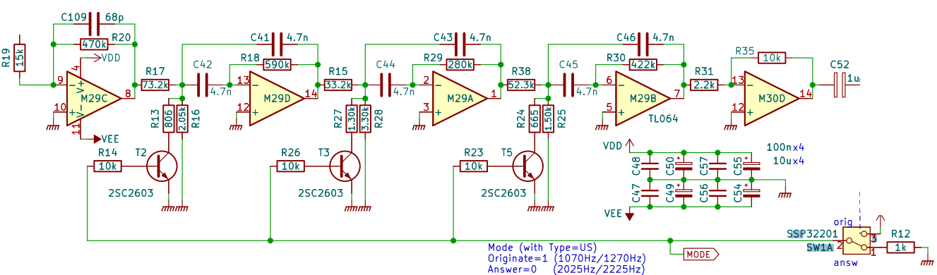
In looking at this, we have to remember this is receiving, so the frequency sets are reversed.
In Answer mode – Stage 1 – C=4.7n, R1a=73.2k, R1b=2.05k, R2=590k – results in fo= 987Hz, BW=721Hz
Stage2, C=4.7n, R1a=33.2k, R1b=3.3k, R2=280k – results in fo=1.21Khz, BW=1.5Khz
Stage3, C=4.7n, R1a=52.3k, R1b=1.5k, R2=422k – results in fo=1.37Khz, BW=1Khz
In Originate mode, Stage 1- C=4.7n, R1a=73.2k, R1b=2.05k, R2=590k – results in fo=1.84Khz, BW= 721Hz
Stage2, C=4.7n, R1a=33.2k, R1b=3.3k, R2=280k – results in fo=2.11Khz, BW=1.5Khz
Stage3, C=4.7n, R1a=52.3k, R1b=460R, R2=422k – results in fo=2.4Khz, BW=1Khz
Receive Changes for CCITT V21
For V.21 we want the low receive pair centred on 1080 Hz, from 980 and 1180 Hz, and the high pair centred on 1750 Hz, from 1650 and 1850 Hz.
The original three filters do not all sit exactly on the FSK tones. They form a broader three-stage response around the wanted band. So rather than making all three stages 1080 or 1750 Hz, I would retain approximately the same spread.
That gives sensible V.21 targets of about 905Hz, 1080Hz and 1255 Hz for the Low Band and 1570Hz, 1750Hz and 1920 Hz for the High Band.
If we keep the original 4.7 nF capacitors and R2 values, we end up with:
Stage 1, R2 590 kΩ: low-band R1 ≈ 2.37 kΩ, high-band effective R1 ≈ 788 Ω.
Stage 2, R2 280 kΩ: low-band R1 ≈ 3.51 kΩ, high-band effective R1 ≈ 1.34 kΩ.
Stage 3, R2 422 kΩ: low-band R1 ≈ 1.73 kΩ, high-band effective R1 ≈ 737 Ω.
Because the high-frequency setting is obtained by switching another resistor in parallel, the required switched resistors become approximately:
R13 ≈ 1.18 kΩ
R27 ≈ 2.16 kΩ
R24 ≈ 1.29 kΩ
with the main resistors approximately:
R16 ≈ 2.37 kΩ
R28 ≈ 3.51 kΩ
R25 ≈ 1.73 kΩ
So, 6 simple resistor substitutions and a couple of re-routed traces, and the modem now operates beautifully with CCITT V21. I can positively confirm, as I used it a *lot* cross legged on the floor wherever I could find a spare phone line.
I can share this now, because the entire phone network is digital now, and those affected are long gone 🙂 🙂
Having successfully modified it, I naturally put this new capability to entirely sensible and responsible use.


