(or how I made a nice balun that should last a while)
Inspired by an email I saw recently advertising the Chameleon 40/20 antenna (https://chameleonantenna.com/shop-here/ols/products/cha-4020-fd), as well as a review I saw on the HamRadioConcepts Youtube Channel by Eric, KJ4YZI, I spent some time making a similar antenna using components that I purchased from Bunnings and Jaycar. It’s performance on air was wonderful, even when installed in the backyard at only 8m in an inverted V configuration.
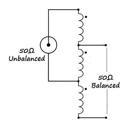
The balun design I chose was an air wound 1:1 voltage Balun, to transform the 50ohm unbalanced coaxial feeder into a 50ohm unbalanced dipole feed. I elected to make a balun, as I needed a centre insulator that would be robust.
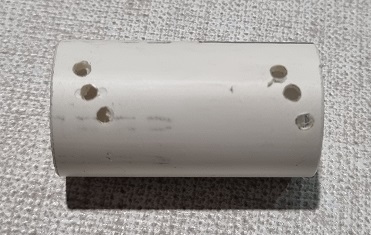
I used a 35mm long section of 25mm diameter length of PVC pressure pipe as the former, and drilled a set of holes for the three windings. Because I had 1mm diameter copper wire available, I determined that the length of the three windings would be 27mm, so I spaced the holes apart about 28mm.
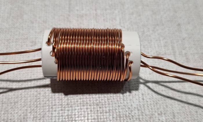
Next, I wound three sets of windinge, 9 turns each.
Using some heatshrink tubing, I connected the windings in series. It is important to be careful to scrape the insulation from the wore as well as ensure that the mechanical joint is robust before it is soldered.
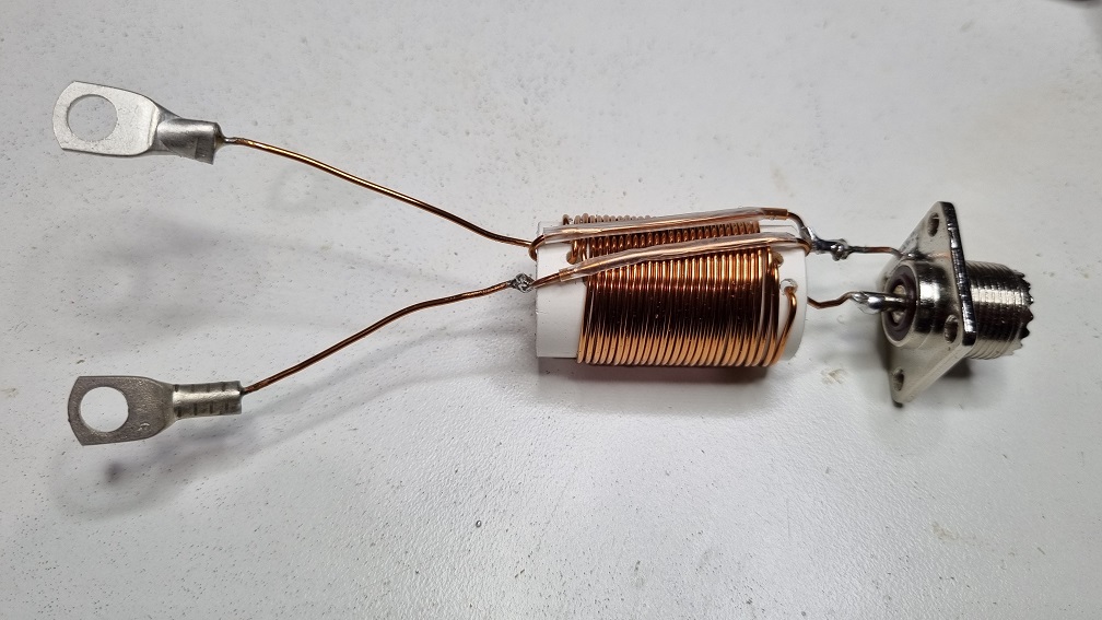
Once the balun was complete, I soldered it to a SO239 connector and a set of 6mm diameter wire lugs. Using fully soldered joints for the SO239 ensures that electrical connectivity is assured even is a screw connection becomes loose. Remember to scrape the coating off the edge of the SO239 for the ground connection. That completed the physical construction of the balun.
Next, I drilled a 25mm diameter hole in a 42mm PVC endcap. That allowed me to mount the SO239 inside an enclosure using some 3mm x 25mm long screws. Remember to include spring washers to keep the nuts from loosening over time.
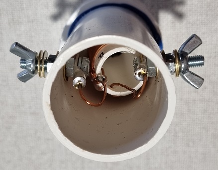
I cut an appropriate length of 42mm diameter pressure pipe to allow the terminals for the dipole to me installed. These were made from a 6mm x 25mm screw and a set of nuts and lockwashers. I was careful to ensure that the terminal was attached to the balun lugs using a nut and lock washer so that it would not become loose inside the enclosure. In all, each terminal consisted of a screw, wire terminal, lock washer, nut, lock washer, PVC pipe, flat washer, nut, two flat washers and finally a wingnut. Ideally these should all be stainless steel.
The bottom end cap with the SO239 was glued to the pipe to ensure a watertight seal. It is worth noting that any moisture can drain past the edge of the SO239.
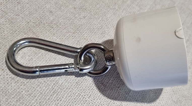
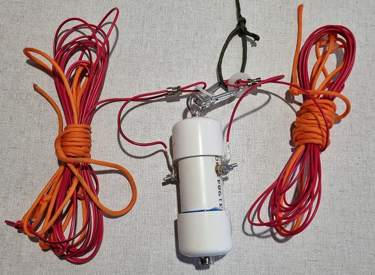
Finally, I attached an eyebolt to the top cap using a m6 nylock nut to ensure that it doesn’t become loose. I used a self closing carabiner hook to allow for mounting as well as strain relief.
The final assembly is not too bad. When I am happy that there are no issues, I will glue the end cap in place. Until then, it is a good friction fit.
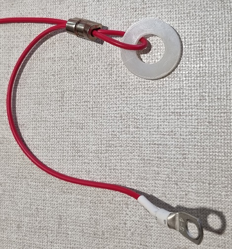
Next step was to make the elements. I started by making a temporary set of 20M elements from heavy duty wire.
A quick calculation determined that the 20M band is 20 Metres in length for a full wavelength, so a half wavelength is 10M, meaning that I would need two 5M long ements. Technically the length would be 468/f for the whole dipole (in feet), which works out at 16.7 feet (5.08m). I cut the elements at around 5.8M, knowing I would have to trim them.
I used a nylon washer swaged in place for strain relief, and a soldered lug for the termination. I will be re-making the elements from 1.6mm diameter stainless steel wire when I understand how to solder the stainless steel to the solder lug. 40M elements will be next – probably next weekend.
Using my trusty Buddypole tripod, I hoisted the assembled antenna into the air and secured the ends of the elements using some bright orange paracord for visibility. a quick look at resonant point indicated that the system was resonant at around 12 Mhz. Woot – You can always remove wide. As Dad said – You can always cut wood – adding it back later is painful.
I decided to trim of 30-40cm of cable from both elements, and that dropped resonance up to 13 Mhz. Another trim from both ends increased it to 13.8, and a final trim of about 30mm got it to resonate in the middle of the 20M band (14.1 Mhz) with a SWR of 1.3 to 1, which is expected with an inverted V configuration which has a natural feed impedance of 70 Ohms instead of 50.
A quick listen on the band with my trusty Yaesu FT857 discovered a QSO between a couple of hams located in the USA, even though the local noise level in my back yard was S7.
In all a fun, simple afternoon and I am looking forward to making a set of 40M elements (33 feet – 10.05m) for this and turning it into a fan dipole. I will take it to a quiet location and see who I can chat with. 🙂
/

