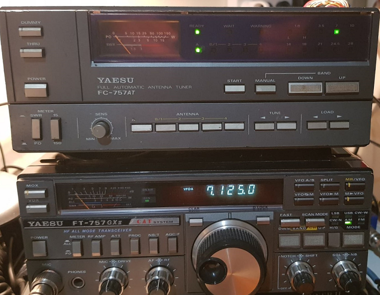
I recently picked up a FC757-AT tuner to compliment my FT757Gx. I got it for an absolute steal, and it turns out that it was because it was faulty 🙂 (You have to love estate sales on eBay). This story outlines the journey that I went on to get the tuner working.
Connecting Cable (FT757 – FC757)
Not being one to let something being faulty worry me, as soon as it arrived, I dived right into it. I started by making a custom cable following instructions on Youtube. Essentially, there are 4 band inputs between the FT757 and the tuner in addition to one ground, one 13.8V supply and one Inhibit line to allow the tuner to tell the radio to reduce its output power.
The pin assignments from the Band data are:
FT-757GX : Band (Rear Panel) : 8 pin JST connector
1 – GND
2 – D : BAND DATA OUT
3 – C : BAND DATA OUT
4 – B : BAND DATA OUT
5 – A : BAND DATA OUT
6 – TX GND (not connected)
7 – +13.5 VDC
8 – INHIBIT
FC-757AT : ACC2 (Rear Panel) : 9-pin Molex (0.062″ pins)
1 – GND
2 – D : BAND DATA IN
3 – C : BAND DATA IN
4 – B : BAND DATA IN
5 – A : BAND DATA IN
6 – NC (not connected)
7 – +13.5 VDC (2)
8 – INHIBIT
9 – NC (not connected)
The pinout of the cable ironically is 1-1, 2-2 , 3-3, 4-4, 5-5, 7-7, and 8-8.
As with all cables, I used Glue Loaded heat shrink to ensure that the cable was unlikely to fail through being mechanically strained.
Initial Identification of Faults
As soon as I created the cable, I plugged it in, and the resounding nature of the phrase “Faulty” reared its ugly head. There were multiple really weird symptoms.
- The device had its ‘WARNING’ lamp permanently illuminated.
- Most of the buttons didn’t do anything.
- The meter bulbs were dead (What 80’s radio isn’t)
- When the device was powered the Load capacitor was permanently rotating.
Theory of Operation
The FC-757 is an automatic impedance matching device utilizing a
modified pi-L network to do the actual matching. At the input to the unit, there is a CM coupler that measures forward and reflected power continuously that the microprocessor in the unit uses to determine whether to make tuning changes.
In the tuner, the Tune and Load capacitors are microprocessor controlled, and the Inductance (L) is a switched inductance based on the band being tuned. There is also a stepped capacitance which is changed with bands (i.e. the input C and band L are changed together with band changes)
As mentioned above, there is a directional coupler on the transmitter side of the network and an RF pickup at the antenna side allow the microprocessor to identify any mismatch, and adjust the Load or Tune capacitances accordingly. According to the manual, whenever the SWR is measured at greater than 1.5:1, the tuner automatically tunes to correct the impedance mismatch.
The CM coupler outputs a DC voltage, on the FWD and REF outputs that is proportional to the power being driven through the unit. An output of approximately 9.6V is present when 100W of RF is passed from input to output with a 50R load.
The microprocessor implements a backup facility that automatically sets the Tune and Load capacitances at the settings that resulted in the lowest SWR reading as the band is changed. Subsequent tuning adjustments are automatically stored in the microprocessor for later use.
Fault Finding
The first step was to examine the user manual in detail, unfortunately it wasn’t much help. It did reassure me that I had installed it correctly, so in I dived.
The first thing replaced was the backup battery – The original from 1985 was outputting about 0.2 volts instead of 3v, so I removed the old battery and installed a battery holder and a shiny CR2032 battery.

I immediately turned it on, and there was no improvement. Everything was borked and the Load capacitor was merrily spinning.
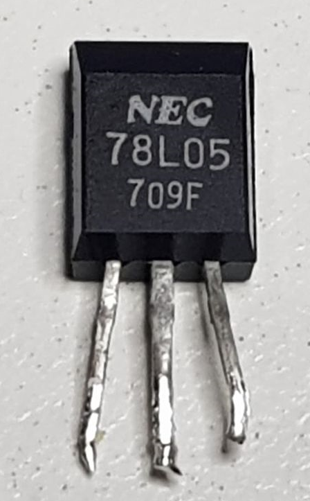
It turns out that the entire device uses a mask programmed microprocessor, a 4 bit cpu (7505) made by NEC. I downloaded the datasheet for the CPU, and discovered that it needed 5v (+/- 10%) to run. A quick measurement of the supply voltage showed that it was being fed by 7.5v. I located the 78L05 voltage regulator and immediately replaced it. This bode poorly for the micro, so I dropped a message onto Facebook to see if anybody else had had a similar issue. Sadly there was not much help.
When I re-tested the unit, there was no change, the device was still dead as a doornail.
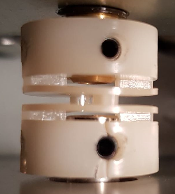
An interesting design feature of the Yaesu FC 757 tuner is that the position of the Load and Tune capacitors is reported to the microprocessor via a set of potentiometers that are directly connected to the drive shaft for the caps. This connection uses a series of flexible couplers, and time has not treated these nicely. The ones on my unit were cracked. This cracking is caused by a combination of the vinyl shrinking over time, coupled by the stresses exerted by the grub screws that secure the couple to the shaft. Fortunately, the cracking allowed the capacitor drive to rotate without causing damage to the potentiometer. I will repair the shaft couplers on a rainy day when I am not working the bands.
With the board removed, I turned the potentiometer to see if the Microprocessor would decide that the capacitor was in the correct position. Sadly no dice – I followed the potentiometer signal into a quad CMOS switch (CD4016) – The signals became really weird using a multimeter and it was not clear that the potentiometer voltage was making it past the switch, so I decided to replace the CD4016. Again re-testing indicated that it wasn’t completely fixed.
I followed the schematic, and saw that the position of the shaft as read by the microprocessor was determined using an interesting arrangement of a Digital – Analog converter made from resistors, driving a comparator, reading the potentiometer value (after the CD4016), ultimately providing an output to the CPU on pin 30 (Comparator Input).
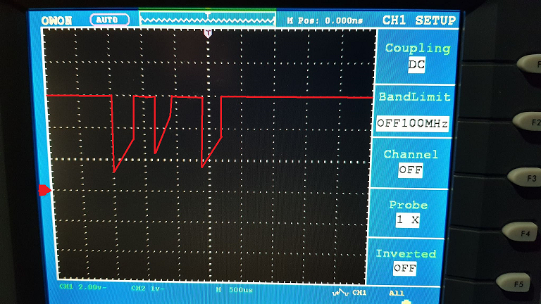
Here was an example of a faulty comparator output signal (which I drew from memory, as I forgot to take a photograph). Note how the level didn’t reach 0v, and the bottoms of the waveforms had a strange slope.
I decided to replace the uPC277C comparator chip with a LM393 that I had in stock that was pin for pin compatible and when I powered up the device, SUCCESS!!!!!! The ‘Load’ Capacitor started moving, and stopped. The waveform on the comparator pin changed completely:
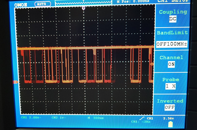
It is very interesting to see the comparator signal – It is clear that the output is microprocessor controlled, with the microprocessor testing multiple inputs per second. Obviously, static DC voltage analysis in this part of the circuit would not be effective.
I followed the manuals instructions for re-calibrating the position of the Tune and Load capacitors, and now the capacitors easily rotate when the < and > buttons are pressed.
Next, the device was still displaying a ‘WARNING’ lamp. I noticed that when I selected various antenna outputs, it would show output ‘A’, combined with Output ‘B4’, which should never be able to be selected as it is an illegal combination.
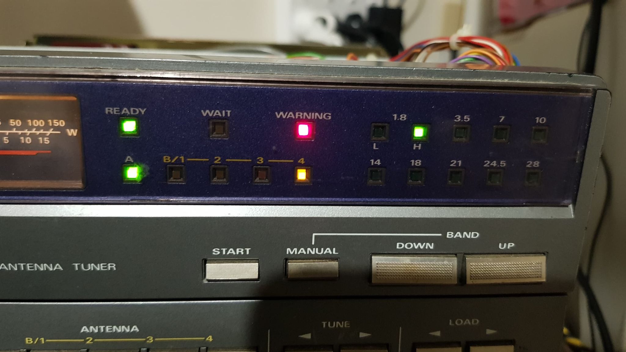
A quick review of the circuit showed that the lamps were driven using a uPA2004C Open Collector output driver. I replaced the device and the display was immediately restored, including the pesky ‘WARNING’ lamp going away.
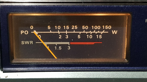
Next, I finished by replacing the meter bulbs. (Jaycar # SL2675 – MiniLamps 12v Large) They seem to be the bane of my existence, and I have never had a piece of gear from the 80’s come past my workbench without needing them replaced. Immediately, the meter was illuminated gently, like I remembered them in my youth 🙂
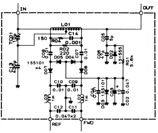
Next, I followed the alignment procedure from the manual and discovered that I could not set the power meter to the 100W position with 100W driving the tuner – at the maximum adjustment position, the meter would only reach 50W. This indicated that there was an issue with the CM coupler. A quick test discovered that all of the 1SS101 schottky diodes within the coupler had been damaged (most likely through overload). These were replaced with 1N5711 diodes and the coupler returned to normal operation.
Further alignment was uneventful, and the Tuner has been restored to working operation.
In all a wonderful afternoon, recovering a beautiful piece of gear that will live on for another 30 years.
Lessons Learnt
I got sidetracked a bit, expecting the microprocessor to go through a complex ‘self test’ as soon as the unit was turned on. In reality, this device will set the Tune and Load Capacitors to the last used position as soon as a band is selected.
A significant amount of worry was caused because I believed that the microprocessor, which is made from Unobtanium, was faulty. I should have pulled the CRO out much earlier to look at waveforms, which would have confirmed that the micro was operating, and it would have also reminded me that DC multimeters are only useful for measuring supply voltages when working with computers.
There was no harm in replacing the comparator as soon as I replaced the CMOS switch, so thats what I should have done. It would have produced an outcome faster.
Remember to take photos of CRO waveforms often for the blog. Having to re-draw them from memory is not as useful as the real thing.
Yaesu makes nice gear – really nice gear.

